Learning how to read automotive wiring diagrams is like learning a new language. Here we’ll talk about what the common symbols stand for so you can take your auto repair game to the next level.
Watch the Diy automotive wiring diagrams video at the bottom of the page to find out how to use this information to pinpoint electrical problems like a pro. Don’t have time to soak up this much knowledge? Yes, you should bookmark this page or share it with a friend.
My Name is Mark and I’m a Certified Master Technician. Wiring diagrams are drawings of electronic systems found in high quality workshop repair manuals.
These diagrams provide the quickest path to success when dealing with complex electrical problems on any vehicle. Therefore, on this page you’ll find in depth definitions for some of the most common symbols used in the industry standard line drawings.

Understanding this visual language leads to faster detection of malfunctions and the capability to solve difficult car problems.
In the electrical schematics to follow you’ll see symbols arranged in a circuit to better reflect the function, power state, and relative location of various components.
In fact, an electrical symbol may have a slight resemblance to the actual component or its main function. It’s important to recognize when you see the solid and dotted lines on the diagram that there’s a major difference between the two.
These lines actually represent current flow in and out of components connection points. However, the abbreviated text labels or codes placed next to the symbols and lines help you out further by providing descriptions or location information.
Automotive Wiring Basic Symbols
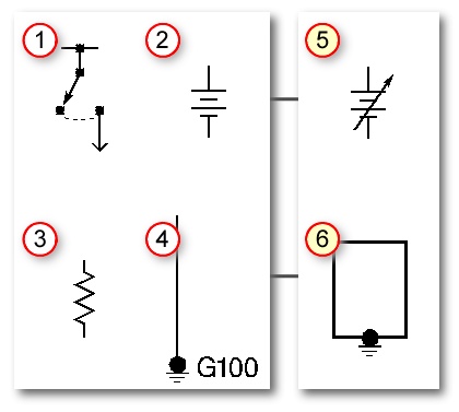
Automotive electrical diagrams provide symbols that represent circuit component functions. For example, a few basic symbols common to electrical schematics are shown as: (1) Switch, (2) Battery, (3) Resistor and (4) Ground.
Note the switch symbol displays an open or closed circuit path, which is what an actual switch performs. The battery symbol appears to be made of layers or plates, common to internal battery construction.
The resistor symbol appears to impede energy flow, which is a resistor function. The G100 ground symbol indicates a connection pointing downward (ground) that dissipates energy. The G100 designation is to help you find this location on the automobile.
Factory service manuals provide component location diagrams including important ground locations. Variations of symbols will exist depending on function or other characteristics. Examples are: Variable Battery symbol (5) and the Case Ground symbol (6). Electrical repair diagrams are mostly standardized for the above symbols.
Auto Wire Diagram Advanced Symbols
Abbreviated codes on the diagrams provide circuit path and part or component information. They use the codes or labels to show circuit connector pin numbers, circuit values or component polarities.
These are standardized throughout the industry. Meaning, they’re the same abbreviated codes found in an Audi service manual or an American car reference book, like the downloadable Chrysler PDF manuals found here on Auto-Facts.org.
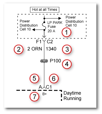
All of these markings work together to add clarity to the diagnostic drawing. Here are a few label examples: (1) A for Amperage or Amps. (2) ORN for wire diameter and color (3) 1340 for Circuit Path ID.
And here are another four notations you’ll find in factory service manuals (4) P for pass through grommet (5) A for Pin ID & Location (6) C1 for Terminal Connector ID (7) B+ for battery positive.
Automotive Wiring Diagrams and Electrical Symbols
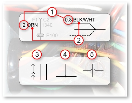
At first glance the repair diagram may not convey how the wires use many colors and diameters. They show the diameter of each wire using a label placed at some point along side its drawn line (1) (0.8). These can take some effort to locate on fold out map type diagram.
Nevertheless, being aware of the color of a wire remains important.(2) They provide wire color information as a color code label, in this case black/white.
(3) Also shown are common schematic illustrations of wires, (4) wires connected and (5) wires crossed but not connected. For consistency most electrical schematics have signal or energy flow from top to bottom.
And component inputs on the left and outputs on the right. With that said, providing an understanding of how a system would function makes the wiring repair diagram one of the most valuable resources a technician can have.
Shop Manuals and Auto Repair Information Availability
Get Access to Professional Diagnostic and Repair Information.
Share this auto repair page and watch the wiring diagram video again.
I wanted to let you know a little more about the way to get the exact Do it yourself wiring diagrams for you’re specific vehicle on the cheap. People ask which one is better a PDF or a subscription service? It’s like the Ford F250 HD and the Chevy Silverado Pick up trucks. Both have loyal fans.
However, factory repair manuals are offered right here. In fact, they start at $9 and go all the way up to 27 bucks at the time of this writing. No coupon code to enter at checkout, because it’s the regular price at this time. Now there’s no excuse not to access the automobile wiring diagrams that professional shops use.
You get the same schematics in dealership manuals, because they pull data from factory publications. You can print out what you need and take them right to the vehicle. So in short, electrical pun intended, you can subscribe to this for a month and find and print all the wiring diagrams for your specific vehicle and have them for life.
Import Pages Related to Shop Manuals
Another update: I have purchased a subscription a workshop manual for my own vehicle so I could make a video demonstration of what it looks like. View the demo video for this program that puts auto repair online.
You’ll find a wide variety of do it yourself automotive information on the page I built dedicated to DIY auto repair tips. More information on the use of automotive wiring diagrams. However, don’t forget this page that reviews 2 golden rules for using electrical troubleshooting manuals.
My latest video on my YouFixCars.com website has some advanced tips for using electrical diagrams to solve car problems. This is the method I use every time I break out a wiring diagram. Find out more about me and this website. Also discover what gives me the right to talk about automotive wiring diagrams. This next link takes you to the auto facts homepage.