Diagnosing complex automotive problems is easier when you understand how the system works.
Here we’ll talk about how they operate so you can check these components out before replacing them. Many computer sensors are the variable resistor type.
This means the resistance will change the reference voltage heading back to the power train control module. With that said, some of the most interesting automotive sensors are the ones that produce their own output voltages.
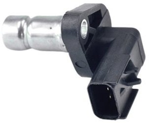
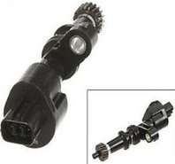
A few popular components that generate their own voltage include the hall effect switch, oxygen sensors, knock sensors that control ignition timing and the popular magnetic pulse generator.
This includes the gear driven speed sensor and the magnetic crankshaft sensor pictured above. Unfortunately, old automotive computer sensors do fail sometimes. Fortunately, most of the above mentioned car parts produce their own voltage. This means testing for output signals becomes a possibility.
This is usually a varying signal that is much like a simplified foreign language. When received by the computer it enables it to monitor and then command adjustments for changes in the engine fuel or ignition systems.
When you have a part fail, few people realize that Amazon offers replacement automotive computer sensors delivered to your door, cheap.
Permanent Magnet Generators
Magnetic pulse generators use the principle of magnetism and field induction to produce a small voltage signal.
They’re also called PM generators. Permanent magnet sensors are often used to send data to the control module to indicate the speed of individual or internal components.
These voltage producing automotive sensors are used in several critical areas of vehicle operation. Not only do these parts increase fuel economy and reduce engine emissions but they are also used in the improvement of driver safety systems.
Just a few examples include dash-mounted instrumentation, cruise control systems, anti-lock brake and automatic traction control systems.
Also some ignition systems, and even the latest in speed sensitive steering systems that are often integrated with automatic ride control or stability components. A magnet based speed sensor is used to provide important information to the computer about the exact position of a monitored device.
This is common in engine controls where the power-train module needs to know the exact position of the crankshaft in relation to other rotational components like the camshaft.
Types of Automotive Computer Sensors
They use the pickup coil in automotive technology for the span of about 15 or 20 years. When this component fails it can cause a hard to diagnose no start condition. Even worse is when these parts fail intermittently.
This can cause misfires, stalling conditions and lack of power. Knowing how a pickup coil works might be helpful during diagnostics or when following symptom tree charts.
The pickup coil is known as a stator type automotive computer sensor and sometimes is nicknamed the pole piece. It consists of a permanent magnet with fine wire wrapped around it. There’s a small air gap between the pickup coil and the timing disk. The amount of this air gap becomes critical to correct operation. However, metal fillings attracted to the magnets reduce the gap.
As the timing disk rotates in front of the pickup coil or pole peace the generator sends a pulse signal to the ignition module. This is produced as a tooth on the timing disk aligns with the core of the pickup coil. it then repels this generated magnetic field.
They force the magnetic field to flow through the coil and pickup core. When the tooth passes the core the magnetic field is able to expand. This action is repeated every time a tooth passes the pole.
The moving lines of magnetic force cut across the coil winding and induce a voltage signal. To simplify this, basically when a tooth approaches the pole piece it produces a positive current as the magnetic field begins to concentrate around the coil.
When the tooth and core are perfectly aligned it stops the expansion or contraction of this magnetic field and the voltage drops to zero. When it passes on the opposite side of the pole piece a negative current forms.
Using Sensor Voltage to Calculate Position
Using these three measurements of positive voltage, zero voltage, and negative voltage, extremely accurate position reporting is accomplished. You can test each individual computer sensor for proper operation with a scan tool or even a volt meter. Favorite this automotive computer sensor page or share with friends.
Interested in learning more about how to read scan tool data? Visit my page about using the scanner to diagnose automotive computer sensors. the homepage is up next. Here you can find out what else they covered on this car fans website. You can also locate some answers to a variety of car questions.